Science Behind High-Speed Optical Fiber

What’s the Science Behind High-Speed Optical Fiber—From Raw Materials to Finished Products?
When we stream 4K video, join a global video call, or access cloud AI models in real time, it’s easy to forget the quiet miracle beneath it all: a hair-thin strand of glass, stretching across oceans and cities, guiding pulses of light with near-perfect fidelity. But this “magic” isn’t magic at all. It’s the result of centuries of optics, decades of materials science, and relentless precision engineering—all converging to turn sand into speed.
So how does high-speed optical fiber go from raw materials to the backbone of the internet? What scientific principles enable it to carry terabits per second across continents? And why can’t we just use any glass?
Let’s walk the full path—from silica sand to live network—with the depth and respect this foundational technology deserves.
Where Does Optical Fiber Begin? (Hint: It’s Not in a Lab—It’s in the Earth)
It starts with silica sand—specifically, quartz (SiO₂) with extremely low iron and hydroxyl content. But not just any beach sand will do. High-purity quartz must contain less than 1 part per million (ppm) of metallic impurities, because even trace iron or copper absorbs light and creates loss.
To achieve this purity, manufacturers use synthetic silica made via chemical vapor deposition (CVD). The most common method is Modified Chemical Vapor Deposition (MCVD):
- A hollow pure silica tube (the future cladding) is rotated in a lathe.
- Gases like silicon tetrachloride (SiCl₄), germanium tetrachloride (GeCl₄), and oxygen are injected inside.
- A traversing oxy-hydrogen torch heats the tube to ~1900°C, causing the gases to react and form fine glass soot:
SiCl₄ + O₂ → SiO₂ + 2Cl₂
GeCl₄ + O₂ → GeO₂ + 2Cl₂ - The soot deposits on the inner wall and fuses into a thin, doped glass layer.
Germanium dioxide (GeO₂) is added to the core because it increases the refractive index—creating the optical contrast needed for total internal reflection. Fluorine may be added to the cladding to lower its index, enhancing light confinement.
This isn’t chemistry alone—it’s atomic-scale architecture. The core’s refractive index must be precisely 0.3–0.5% higher than the cladding. Too little, and light leaks; too much, and nonlinear effects or manufacturing stress arise.
How Do You Turn a Glass Tube Into a Kilometer of Fiber?
Once the soot layers are deposited, the tube is collapsed into a solid preform—a thick glass rod about 2 meters long and 20 mm in diameter. This preform is a 1:1 scaled model of the final fiber: its core/cladding geometry and doping profile are already locked in.
The preform is then loaded into a drawing tower—a marvel of thermal and mechanical control:
- The tip is heated to 2200°C in a graphite or zirconia furnace until it melts.
- A molten glass droplet forms and is pulled downward by gravity and capstan wheels.
- As it cools, it’s drawn into fiber at speeds up to 50 meters per second—thinner than a human hair (125 µm cladding, 9 µm core for single-mode).
- Immediately after drawing, the fiber passes through a dual-layer coating applicator:
- A soft inner buffer (typically UV-cured acrylate) cushions microbending.
- A harder outer jacket provides mechanical protection.
- UV lamps instantly cure the coatings, and the fiber is spooled onto drums.
Throughout this process, laser micrometers monitor diameter in real time (tolerance: ±0.5 µm), while tension sensors prevent breakage. A single preform can yield over 200 kilometers of fiber—each meter a perfect replication of the preform’s design.
This is materials science at industrial scale: turning a static glass rod into a continuous, defect-free waveguide longer than most cities.
What Makes Fiber “High-Speed”? It’s Not Just Bandwidth—It’s Physics
All fiber carries light—but high-speed fiber is engineered to preserve signal integrity over distance and data rate. Three scientific principles define its performance:
1. Low Attenuation: Letting Light Travel Farther
The primary loss mechanisms are Rayleigh scattering (from molecular-scale density fluctuations) and infrared absorption (from silica’s molecular vibrations). Modern single-mode fiber achieves 0.17 dB/km at 1550 nm—meaning light can travel ~100 km before losing 98% of its power. This low-loss window is why 1550 nm is the standard for long-haul systems.
2. Controlled Dispersion: Keeping Pulses Sharp
As light pulses travel, they spread due to chromatic dispersion—different wavelengths move at slightly different speeds. In standard SMF (ITU-T G.652), dispersion is ~17 ps/(nm·km) at 1550 nm. For 10G systems, this limits reach to ~60 km; for 400G, it’s catastrophic.
Solution? Dispersion-optimized fibers:
- Non-Zero Dispersion-Shifted Fiber (NZ-DSF, G.655): Small, controlled dispersion suppresses nonlinear effects in DWDM.
- Large Effective Area Fiber (LEAF): Reduces power density, minimizing SBS and FWM.
- Ultra-low-loss (ULL) fiber: Uses purer silica and reduced Rayleigh scattering for transoceanic cables.
3. Polarization Stability: Critical for Coherent Optics
In 100G+ coherent systems, data is encoded in light’s phase and polarization. Random birefringence in fiber scrambles this—unless polarization-mode dispersion (PMD) is minimized. High-speed fiber is drawn under strict tension control to ensure core circularity and low PMD (<0.05 ps/√km).
In short: high-speed fiber isn’t “faster”—it’s smarter glass, designed to cooperate with advanced modulation and DSP.
How Do You Know the Fiber Works Before It Leaves the Factory?
Rigorous testing ensures every spool meets global standards (ITU-T, IEC, Telcordia):
- Attenuation: Measured via cut-back or OTDR at 1310, 1550, and 1625 nm.
- Mode Field Diameter (MFD): Verified by near-field or far-field scanning—critical for low splice loss.
- Geometry: Core/cladding concentricity, diameter, and ovality measured to sub-micron accuracy.
- Proof Testing: Every fiber is stressed to 100 kpsi (0.7 GPa) to weed out weak points—ensuring 25+ year reliability.
- Hydrogen Aging Tests: Expose samples to high temp/humidity to predict long-term darkening.
Only after passing these does fiber earn its grade: G.652.D, G.654.E (for submarine), G.655, etc.
From Spool to System: How Fiber Becomes a Product
Raw fiber isn’t deployed naked. It’s engineered into cable architectures for specific environments:
- Indoor cables: Tight-buffered, fire-retardant, flexible for patch panels.
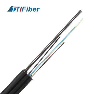
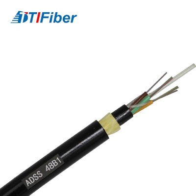
- Outdoor loose-tube cables: Fibers float in gel-filled tubes, protected by aramid yarn and steel armor—immune to moisture and rodent damage.
- Submarine cables: Hermetically sealed, copper-powered, with multiple fiber pairs and steel wire armoring to survive 8,000 meters underwater.
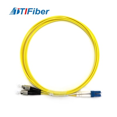
Then come connectors (LC, SC, MPO), splice closures, and amplifiers (EDFAs). Only when integrated into a system—paired with coherent transceivers, DSP, and network control—does the fiber fulfill its purpose.
Why This Science Matters
Behind every Zoom call, financial trade, or telehealth session is a cascade of scientific choices made decades ago—and refined daily:
- Choosing germanium over phosphorus for doping.
- Optimizing draw speed to reduce frozen-in stress.
- Designing APC connectors to eliminate back reflection.
High-speed optical fiber isn’t born from a single breakthrough. It’s the accumulated wisdom of physics, chemistry, and engineering, all focused on one goal: guiding light with minimal betrayal.
And as we push toward 1.6 Tbps per wavelength and hollow-core fibers that guide light in air, the journey from raw materials to product will only grow more astonishing.
But the core truth remains unchanged: the future isn’t just digital—it’s photonic. And it all begins with a grain of sand, heated, stretched, and shaped into a path for light.
Differences Between Armored and Unarmored Fiber Optic Cable
Why Does Not Light Just Leak Out the Sides of the Fiber
Related Article