How to Manufacturing Low-Loss Optical Fiber
Manufacturing Low-Loss Optical Fiber Genesis of Light Speed
The information superhighway relies on a remarkable material: low-loss optical fiber. These hair-thin strands of glass transmit vast amounts of data at the speed of light, forming the backbone of global communication. But how are these seemingly simple threads manufactured with such incredible precision and purity to achieve their extraordinary performance? It's a testament to advanced materials science and sophisticated engineering processes.
The creation of an optical fiber is a multi-stage journey, beginning with ultra-pure raw materials and culminating in a meticulously drawn fiber. The core challenge is maintaining absolute purity and precise geometric control throughout.
Stage 1: Preform Fabrication – The Heart of Purity
The journey begins not with a fiber, but with a "preform" – a larger, meticulously crafted glass rod that will be subsequently drawn down into hundreds or even thousands of kilometers of optical fiber. The preform dictates the core and cladding properties of the final fiber, making its fabrication the most critical stage for achieving low loss. The primary goal here is to create a glass structure with the precise refractive index profile needed for guiding light, while eliminating impurities that could absorb or scatter the optical signal.
Two dominant techniques for preform fabrication are:
1. Modified Chemical Vapor Deposition (MCVD)
This is a widely used and highly controlled method:
- Process: A high-purity silica tube (the cladding material) is rotated in a lathe. Gases containing precursors like silicon tetrachloride and germanium tetrachloride are introduced into the tube. A torch external to the tube traverses its length, heating the glass to around 1600-1800 degrees Celsius.
- Reaction: The heat causes a chemical reaction (oxidation) of the precursors, forming microscopic glass particles (soot) of silica and germanium dioxide on the inner wall of the tube.
- Consolidation: As the torch moves, it fuses these soot layers into a dense, transparent glass. By varying the concentration of germanium tetrachloride in subsequent passes, the refractive index profile is carefully built up layer by layer, with the highest concentration (and thus highest refractive index) deposited for the core.
- Collapse: Once sufficient layers are deposited, the tube is heated to a higher temperature, causing it to collapse into a solid glass rod – the preform. The hole that remains becomes the high-index core, surrounded by the lower-index cladding.
2. Vapor Axial Deposition (VAD)
VAD is a flame hydrolysis process that builds the preform axially:
- Process: Instead of depositing inside a tube, VAD builds the preform from an "end." A mixture of precursor gases (like silicon tetrachloride and germanium tetrachloride) is fed into a flame (typically oxy-hydrogen).
- Reaction: The flame hydrolyzes these precursors, creating fine glass soot particles. These particles are directed onto the end of a rotating silica seed rod.
- Growth: The rod is continuously pulled upwards at a controlled rate while the soot accumulates, forming a porous preform in the axial direction. The refractive index profile (core/cladding) is achieved by carefully controlling the gas flow rates of the dopants during deposition.
- Consolidation: The porous preform is then moved to a separate furnace where it is heated in a chlorine atmosphere to dehydrate it (remove hydroxyl ions, a major source of loss) and then consolidated into a clear, dense glass rod.
| Step | Method(s) | Key Action | Goal |
| Vapor Deposition | MCVD (Internal) or VAD (Axial) | High-purity gases (like Silicon Tetrachloride and Germanium Tetrachloride) react to deposit layers of glass soot. | Establish the exact refractive index profile (high-index core, low-index cladding) and eliminate impurities. |
| Consolidation | Heating | The porous soot structure is intensely heated (often in a chlorine atmosphere) and densified. | Convert the soot into a solid, transparent, bubble-free glass rod. |
| Collapse (MCVD) | Final Heating | The glass tube shrinks inward to form a solid rod. | Form the final preform ready for drawing. |
Stage 2: Fiber Drawing – From Rod to Thread
Once the preform is meticulously crafted and consolidated, it's ready for the fiber drawing process. This is where the large preform is attenuated into the microscopic fiber.
- Process: The preform is loaded vertically into a high-temperature drawing tower furnace, typically heated to around 1900-2200 degrees Celsius.
- Softening & Drawing: The tip of the preform softens in the furnace, forming a molten "gob." A thin strand is pulled from this gob, called the "fiber."
- Diameter Control: The fiber is continuously pulled downwards by a capstan (a rotating wheel) at speeds of several meters per second. Laser micrometers continuously monitor the fiber's diameter, and a sophisticated feedback loop adjusts the drawing speed or preform feed rate to maintain a consistent diameter (typically 125 micrometers, or about 0.005 inches, for standard telecommunication fibers).
- Coating Application: Immediately after leaving the furnace, and while still hot, the bare glass fiber is run through one or two liquid polymer coating applicators. These UV-curable acrylate coatings protect the delicate glass surface from abrasion, moisture, and micro-bending, which can cause significant signal loss. The coatings are then rapidly cured using UV lamps.
- Winding: Finally, the coated fiber is wound onto large spools for further processing and cable manufacturing.
| Step | Location | Key Action | Goal |
| Heating/Softening | Drawing Furnace (1900-2200C) | The tip of the preform is heated until it becomes molten. | Prepare the glass for pulling into fiber. |
| Drawing & Monitoring | Drawing Tower | A thin strand is pulled from the molten tip at high speed. Laser gauges monitor and adjust the pull speed. | Maintain a precise and constant 125-micrometer diameter. |
| Coating | Coating Applicator/UV Lamps | The bare glass fiber immediately passes through liquid polymer and is cured with UV light. | Apply a protective primary and secondary acrylate coating to prevent micro-bends and mechanical damage. |
Stage 3: Testing and Cabling – Ensuring Performance
After drawing, the individual fibers undergo rigorous testing for:
- Attenuation: Measuring signal loss over distance at various wavelengths.
- Bandwidth/Dispersion: Assessing the fiber's capacity to carry information without signal degradation.
- Tensile Strength: Ensuring the fiber can withstand mechanical stress.
- Geometric Uniformity: Verifying core and cladding diameters, concentricity, and ovality.
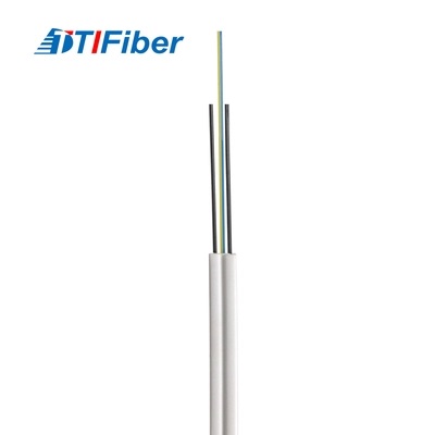
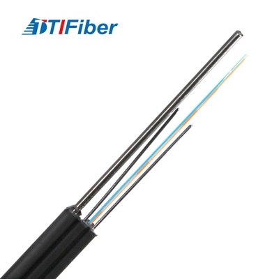
Finally, multiple fibers are often bundled together with strength members (like aramid yarns) and outer jackets (typically polyethylene (PE) or polyvinyl chloride (PVC)) to form robust optical fiber cables suitable for diverse environments, from underground conduits to submarine deployments.
The manufacturing of low-loss optical fiber is a marvel of precision engineering, where control over purity, temperature, and geometry at every stage is paramount. It's this dedication to perfection that allows light to travel thousands of kilometers with minimal degradation, powering the digital age.
| Step | Action | Key Metric | Goal |
| Testing | Optical Measurement | Measure Attenuation (loss/km), Dispersion (signal spread), and Tensile Strength. | Ensure the fiber meets industry standards for low-loss performance. |
| Cabling | Bundling/Jacketing | Multiple fibers are stranded with strength members (e.g., Aramid yarn) and encased in an outer jacket (PE or PVC). | Create a robust cable package suitable for harsh installation environments. |

Low-Loss Optical Fiber From Raw Materials to Final Product
How Do You Actually Quantify These Losses in Practice
Related Article