



How is Optical Fiber Attenuation Calculated?
author: TTI Fiber
2024-10-10
Optical Fiber Chromatography Comparison
Accurate measurement and calculation of optical fiber links are crucial steps in validating network integrity and ensuring performance during fiber optic installation. Due to light absorption and scattering, significant signal loss occurs within the fiber (referred to as fiber loss), which can affect network reliability.
So, how is optical transmission and fiber loss calculated?
When fibers are fused, chromatography may also be used for sorting the fibers.
Explanation of Fiber Optic Natural ColorNatural Color
Generally, optical fibers come in 12 colors: blue, orange, green, brown, gray, white, red, black, yellow, purple, pink, and lime green. These colors are not the natural hues of the fiber but rather the result of dyeing, primarily aimed at differentiating the fibers and enhancing their tensile strength. The actual fiber, made from silica, is colorless and transparent.
Fiber Optic Chromatographic Arrangement
Fiber Optic Cable Color Sequence
The typical color sequence for fibers numbered 1# to 12# is as follows: blue, orange, green, brown, gray, white, red, black, yellow, purple, pink, and lime green. If the cable contains fewer than 12 fibers, a single bundle, known as the central bundle, can be used.
For example:
- 4 fibers: Blue, orange, green, and brown.
- 12 fibers: Blue, orange, green, brown, gray, white, red, black, yellow, purple, pink, and green.
- 16 fibers: Each color (blue/orange/green/brown) is repeated for the bundles.
- 24 fibers: The same color combinations are repeated to provide adequate coverage.
Some cables may be naturally colored and follow the "red head/green tail" principle, with the largest wire fused first, followed by the smallest.
For new projects, using the same color sequence on both ends is sufficient. However, for repairs or maintenance, it’s essential to understand how the original technicians made the connections, including how each fiber within the core is connected.
Criteria for Fiber Optic Loss
The Telecommunications Industry Association (TIA) and the Electronic Industries Alliance (EIA) have developed the EIA/TIA standards, which outline the performance and transmission requirements for fiber optic cables and connectors. These standards are widely accepted and utilized in the fiber optic industry. The maximum attenuation is typically expressed as the attenuation coefficient of the cable in dB/km.
Fiber Optic Attenuation Calculate Formula
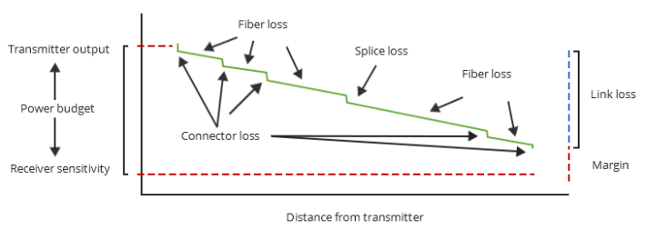
To determine whether an optical fiber link is functioning properly, you need to calculate fiber attenuation, power budget, and power margin, as described below.
1. Formula for Calculating Fiber Attenuation
In fiber optic cabling, it is often necessary to calculate the maximum loss over a defined length of line. The formula for fiber attenuation is as follows:
Total Link Loss (LL) = Cable Attenuation + Connector Loss + Splice Loss (If other components, such as attenuators, are included, their attenuation values can be added).
Cable Attenuation (dB) = Maximum Fiber Attenuation Coefficient (dB/km) × Length (km)
Cable Attenuation Calculator
Connector Loss (dB) = Number of Connectors × Connector Loss (dB)
Connector Loss Calculater
Splice Loss (dB) = Number of Splices × Splice Loss (dB)
Splice Loss Calculator
Total Link Loss (LL) = Cable Attenuation + Connector Loss + Splice LossTotal Link Loss (LL)
Total Link Loss Calculator
As illustrated above, total link loss represents the worst-case scenario for variables within the fiber. It’s important to note that the total link loss calculated is an estimate, as it assumes potential values for component loss, meaning actual fiber attenuation may vary, potentially being higher or lower.

2. Example of Fiber Attenuation Calculation
Consider a single-mode fiber installed between two buildings over a distance of 10 kilometers, operating at a wavelength of 1310 nm. This fiber includes two ST connectors and one splice.
- Cable Attenuation: According to the standard table, the maximum attenuation for outdoor single-mode cable at a wavelength of 1310 nm is 0.5 dB/km. Therefore, the cable attenuation would be:

- Connector Loss: With two ST connectors, each with a maximum loss of 0.75 dB, the connector loss would be:

The actual connector insertion loss can be referenced from the specifications provided by the manufacturer.
- Splice Loss: The TIA/EIA standard specifies a maximum splice loss of 0.3 dB. Therefore, the splice loss would be:

Thus, the total loss for the fiber link would be:

Power Budget Calculate Formula
How does the aforementioned link loss affect the entire transmission? It’s important to introduce another closely related parameter: the power budget. This parameter is used to compare the calculated link loss values to ensure the correct equipment is installed, allowing the link to operate correctly only if the link loss is within the power budget. The power budget (PB) is the difference between the receiver sensitivity (PR) and the optical transmitter power (PT), expressed as:

Assuming the average optical transmitter power is -15 dBm and the receiver sensitivity is -28 dBm, the power budget would be:

Power Budget Calculator
Power Margin Calculate Formula
After calculating the link loss and power budget, the next step is to compute the power margin (PM), which represents the available power after accounting for link loss within the power budget, expressed as:

Using the previously mentioned example of a 10-kilometer indoor single-mode fiber, we find that the power budget is 13 dB and the link loss is 6.8 dB. Therefore, the power margin would be:

This calculated value is greater than zero, indicating that there is still sufficient transmission power within the link.
Power Margin Calculator
What is GYFTY Fiber Cable?
The Essential Benefits of Loose Tube OPGW for Your Power Systems
Related Article
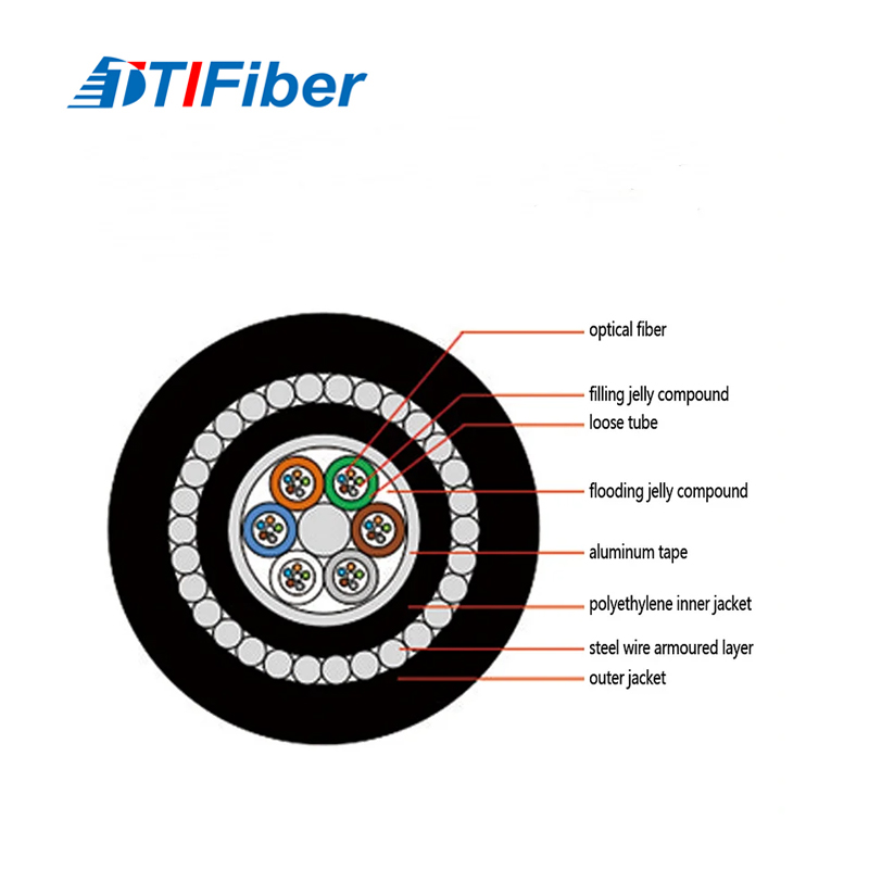
The steel used in SWA cables is not high-carbon tool steel, nor is it brittle cast iron. It is specifically low-carbon (mild) steel wire, typically containing less than 0.25% carbon.
What Kind of Steel Is Used in the SWA Layer

So what exactly does “correct” installation entail? Where do standards draw the line between best practice and code compliance? And why is grounding not just an electrical formality—but a foundational requirement for safety, reliability, and longevity?
What Do Electrical Codes Specifically Require for SWA Grounding
In a market where “SWA” can be loosely applied to substandard products, how do you ensure the cable you’re purchasing will truly perform as expected over its 25+ year design life? Verification isn’t optional—it’s essential. And it must happen before the cable leaves the factory, not after it fails in the field.
How Do You Verify the Quality of SWA Fiber Optic Cable
